Stock, Customer Service, and Tech Support from Anaheim, CA, USA. Shop online and enjoy a wide selection, low prices, and quantity discounts starting at just 10 pieces. Customization and value-added services available. Contact Us.
With reliable performance, quick settling times, precise speed control, and outstanding dynamic accuracy, Anaheim Automation rotary
servo motors are an excellent choice for a wide variety of applications across industries. We offer low-volume users and high-volume OEMs
alike low prices without sacrificing quality.
Select a Rated Power range below to learn more about our Servo Motors >>
A servo motor is a motor which is part of a servomechanism, which can be a DC, AC, or Brushless AC/DC motor. It is typically paired with some type of encoder to provide positioning and speed feedback. Servo motors are controlled via error-correction routines. The term servo can be applied to systems other than servo motor; systems that use a feedback mechanism such as an encoder or other feedback device to control motion parameters.
Servo Motors are best suited for applications where position, torque and speed control are very important. Some applications that a servo motor may be used in would be Robotics, CNC, Textiles (industrial sewing machines), Printing, Solar Tracking Systems, Manufacturing and many others.
Typical servo motor mechanism is not complex. The servo motor has control circuits and a encoder that is connected to the output shaft. The shaft, which is the output device, links to a potentiometer and control circuits that are located inside the servo. The potentiometer, coupled with signals from the control circuits, control the angle of the shaft – anywhere from 0 to 180 degrees, sometimes further. The potentiometer allows the control circuitry to monitor the current angle of the servo motor. If the shaft is at the correct angle, the servo motor idles until next positioning signal is received. The servo motor will rotate the correct direction until the angle is correct.
Each servo motor works off of modulation known as Pulse Coded Modulation, or PCM. The motor has a control wire that is given a pulse application for a certain length of time. The angular degree of the shaft is determined by the length of the pulses, which the servo motor anticipates every couple seconds. A normal servo is mechanically not capable of rotating further due to a mechanical stop built into the main output gear. The amount of power applied to the motor is proportional to the distance it needs to travel. So if the shaft of the servo motor needs to turn a large distance, the servo motor will run at full speed. If the servo motor needs to rotate only a small amount, the motor will run at a slower speed. This is referred to as Proportional Control. The servo motor expects to see a pulse every 20 milliseconds, (.02 seconds) and the length of each pulse will determine how far the servo motor will rotate.
There are two options for Servo Motor feedback controls, either a servo encoder or a servo resolver. A servo encoder and a servo resolver provide the same solution in many applications, but are vastly different. They are both used to sense speed, direction, and position of the Servo Motor output shaft.
Anaheim Automation offers typically offers a 2,500 PPR Incremental Optical Encoder as standard for most Servo Motors like the SMH and SMC models. Although we do offer motors that come attached with Absolute Encoders like the EMJ-ASA/ASB, EMG-ASA/ABS, and some SMS motors. Anaheim Automation also offers custom options in order to get the best encoder suited for your application.
The optical encoder on the Servo Motor uses a rotating shutter to interrupt a beam of light across an air gap between a light source and a photodetector, over time the wear associated with the rotating shutter reduces the longevity and reliability of the encoder. The application will determine whether a resolver or an encoder is needed. Encoders are more accurate and are easier to implement so they should be the first choice for any application. The only reason to choose a resolver is environmental concerns and longevity requirements.
The absolute encoders on a Servo Motor use a unique code for each shaft position. The benefit of this technology is that in the event of losing power the driver will still be able to identify the true position of the output shaft while incremental encoders cannot. This allows the applied system to eliminate the need of a homing system. The absolute encoder only needs to use a reference from point-to-point. This kind of encoder is needed for the kinds of applications where true position is key. Absolute encoders add safety to certain applications; where the loss of position can cause injury.
Resolvers use a second set of rotor and stator coils to induce rotor voltages across an air gap. There are no electronic components used in the construction of resolvers, making them more robust than encoders. Servo resolvers are inherently shock-resistant and operate at higher temperatures than encoders, making them well-suited for harsh environments.
Servo motors operate on negative feedback, meaning that the control input is closely compared to the actual position via a transducer. If there is any variance between physical and wanted values, an error signal is amplified, converted, and used to drive the system in the direction necessary to reduce or eliminate error. Servo motors are controlled by a pulse of variable width that is sent from a micro-controller output pin to the servo motor's control wire. The shaft angle is determined by the duration of the pulse, also known as pulse width modulation (pwm). This pulse has to h ve specific parameters such as; minimum pulse, a maximum pulse, and a repetition rate. Given these constraints, neutral is defined to be the position where the servo has exactly the same amount of potential rotation in the clockwise direction as it does in the counter clockwise direction. It is important to note that different servo motors will have different constraints on their rotation, but they all have a neutral position, and that position is always around 1.5 milliseconds (ms).
Anaheim Automation offers
AC Servo Drives
providing high speed DSP. These servo motors are equipped with auto disturbance rejection control and speed observation control algorithm, in addition to compensation servo delays, forward feed control, and reference smoothing techniques. Anaheim Automation Servo Drives are equipped with a range of dynamic features:
Communication Interface
Standard CAN bus interfaces are available in the FDS AC Servo Driver, simplifying the integration process. Anaheim Automation AC Servo Drivers can also communicate with a PLC, DCS, intelligent instruments,
touch screens
, and more.
Protection Functions
Over and Under voltage protection, motor over heat protection, short circuit protection, and driver over heat protection.
Kinco+ and ESView Communication Software
Anaheim Automation software is capable of the following:
Parameter Management - Fast and convenient operations to all parameters available, including editing, transmission, comparison, and initialization.
Monitoring - Real time monitoring of all I/O signals, alarms of the present and history records, and system status
Real Time Management - Real time sampling of the torque vs. speed curves for simple, rapid analysis.
Real time oscilloscope, tuning, and I/O
Anaheim Automation servo motor brakes operate by applying the force of a spring to a friction plate mounted to the motor shaft. During operation, when power is applied, the brake is disengaged, allowing the motor to rotate freely. When power is removed, the brake is activated, immobilizing the motor shaft and creating holding torque. This allows the motor to support a load even if power is cut, which can be a great safety feature for many applications. Many of our servo motors include a brake option which can typically be located in the "Ordering Information" section of each motor series page. Additionally, we carry four series of friction brakes which can be purchased separately, or be assembled as motor adders. Servo motor brakes may require specific cables for operation. If you have any questions regarding the accessories required for your application, please contact our applications engineers for assistance.
Stepper Motor versus Servo Motor
Stepper Motor Advantages
Servo Motor Advantages
Stability: A stepper motor can drive a wide range of frictional and inertial loads. Does Not Require Feedback: The stepper motor also acts as the position transducer. Price: Relatively inexpensive. Standardized: NEMA standard frame sizes and performance. Plug and Play Features: Easy setup and use. Safety: The stepper motor stops if there is a malfunction or interference. Excellent Low Speed Torque: The stepper motor has the ability to drive several loads without gearing. Repeatability: Accurately returns to the same location - open loop system. Overload Safe: A mechanical overload cannot damage the stepper motor. Longevity: If the specifications of the motor are not exceeded, the stepper is good for 10,000 hours of operation.
High Output: Power in relation to the servo motor size and weight. Encoder: Determines the accuracy and resolution of the servo motor. High-Efficiency: The servo motor can approach 90% efficiency for light loads. High Torque-to-Inertia Ratio: The servo motor can rapidly accelerate loads. A servo motor also:
has 2-3 times continuous power for short periods
has 5-10 times rated torque for short periods
stays cool because current draw is proportional to load
maintains usable high speed torque of 90% of NL RPM
performs quietly at high speeds
has resonance-free and vibration-free operation
Stepper Motor Disadvantages
Servo Motor Disadvantages
Low Efficiency:A stepper motor draws enough power regardless of load.
Torque drops quickly with speed.
Requires microstepping to move smoothly; prone to resonance problems.
There is no feedback to indicate missed steps.
Low torque-to-interia ratio; cannot accelerate loads very quickly.
In high performance configurations, the stepper motor can get extremely hot (requires heat sink or fan-cooled installation).
Motor does not "pick up" after momentary overload.
At moderate to high speeds, the stepper motor can be noisy, which limits its use in certain applications.
Low output power for size and weight.
Poor Motor Cooling: Ventilated servo motors are easily contaminated.
Higher cost.
The servo motor requires "tuning" to stabalize feedback loop.
Safety circuits are required; motor "runs away" when something breaks.
A servo motor is mroe complex and requires an encoder.
The life of a servo motor, used within specifications, is only 2,000 hours. After that, maintenance is required.
Peak torque is limited to a 1% duty cycle.
Sustained overload can damage the servo motor.
Overwhelming choice of motors, encoders, and servo drivers.
Power supply current 10 times average to use peak torque.
The servo motor develops peak power at higher speeds; gearing is often needed.
The question, “what is the difference from a servo motor vs. DC motor” can be answered simply by referring to the definition of the term “servo.” The defining feature of a servo motor is the use of feedback to allow precise control of torque, speed, shaft position, and velocity capabilities. A servo motor can either be a DC or an AC motor. High-performance industrial type servo motors also require a sophisticated controller that can provide these precise instructions to the motor. Whether the servo motor is considered DC or AC just defines the form of power the servo motor runs on. A DC motor’s difference from a DC servo motor is that a DC motor does not have precise torque, speed, or shaft position control by itself. A DC brushed motor does not require a driver or amplifier in order to operate. A DC brushed motor only has a positive and negative terminal where the power supply must be wired to in order to operate and are very inexpensive. The benefit of brushed DC motors is that they provide a low-cost solution in applications where torque, speed, and position do not need to be precisely controlled. Brushless DC motors – also known as BLDC motors – have longer lifespan and greater efficiency than Brushed DC motors, but they are usually more expensive.
The difference between any AC motor and any DC motor is the power source. AC motors use alternating current (AC) and DC motors are powered by direct current (DC). When we talk about DC servo motors, we are typically referring to the types of brushed DC motors used in lower-power, lower-precision servo applications, such as RC cars or planes. Brushed DC servo motors are the least expensive type of servo motor, but the carbon brushes used in their construction degrade with use, so these types are prone to maintenance every 2000 hours of operation. A DC servo motor may also be brushless. Brushless DC (BLDC) servo motors may be found in lower-power industrial applications. Like BLDC servo motors, AC servo motors – typically used in high-power, high-precision industrial applications – are brushless. Any brushless motor type will be less susceptible to the routine maintenance associated with brushed motors. Control method is another notable distinction between AC and DC servo motors. A DC Brush servo motor uses PWM control circuitry to vary the current through a single phase, whereas AC servo motors are controlled through sinusoidal currents of three phases. DC servo motors lack the complex control circuitry required for the sophisticated three-phase control used with industrial AC servo motors.
The vast majority of servo motors we offer are permanent magnet AC motors, but we do offer a select few brushless DC servo motors within the
50-100W Rated Power range.
Our Servo Motors are wound in a Star Configuration. These motors are also PMSM (Permanent Magnet Synchronous Motors) and they are controlled through sinusoidal waveforms.
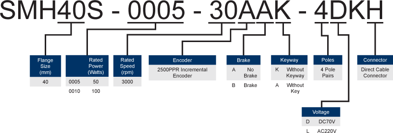
Anaheim Automation servo motors will have either 6 or 8 poles, model dependent. EMG, EMJ, and EML series motors have 4 pole pairs, or 8 poles total. For SMH, SMS, and SMC series motors, the number of pole pairs is indicated by either a "3" or a "4" in the last section of their complete part number.
Example:
Anaheim Automation's packaged Servo Systems offer the FDS and ProNet-E servo drives. FD drives are matched with SMH, SMS, and SMC motors, while ProNet-E drives are matched with EMJ, EMG, and EML motors. Each system features one power cable, one encoder cable, one communication cable, as well as highly functional, easy-to-use software for easy start up. The latest versions of the software can be downloaded directly from our
Software
page; simply locate your servo drive series under the "Models" column and click to download the corresponding software. The servo motors are IP65-rated and equipped with a 2500 PPR, wire-saving incremental encoder. Some Motors come equipped with absolute encoders and brakes.
Install servo motors, drivers and controllers, as well as other electronic and mechanical components, in an environment which is free from electrical noise, vibration and shock.
It is preferable to work with these products in a non-static, protective environment. Please refer to the detailed discussion of EMI in the
installation section
of our web site.
Exposed circuitry should always be properly guarded and/or enclosed to prevent unauthorized human contact with live circuitry.
IMPORTANT NOTE: No work should be performed while power is applied. DO NOT plug in or unplug any connectors when power is ON.
Wait for at least 5 minutes before doing inspection work on the motion control system after turning power OFF, because even after the power is turned off, there will still be some electrical energy remaining in the capacitors of the internal circuit of drivers and controllers.
Read the user's guides that are available on our web site for each product purchased.
Do not operate a motion control system in the presence of flammable gases, dust, debris, oil, vapor or moisture/condensation.
For outdoor use, servo motors, drivers and controllers, and other electronic and mechanical components must be protected from the elements by an adequate cover, while still providing adequate air flow and cooling. Moisture may cause an electrical shock hazard and/or induce system breakdown. Due consideration should be given to the avoidance of liquids, moisture and vapors of any kind. Contact the factory should your application require specific IP ratings.
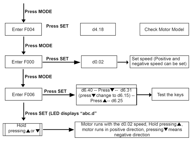
There are several ways to test servo motors. In this example, we will use the Jog Function of the FDS driver to test the Driver, Motor and Cables.
Please make sure the correct wiring of STO before using trial operation, or the driver will display error 200.0.
Press MODE to enter Group F004. Select the object address “d4.18”, and check the motor type.
Press MODE to enter Group F000. Select the object address “d0.02”, and set the target speed to “SpeedDemand_RPM".
Press MODE to enter Group F006. Arrange a test for keys, with the default value of d6.40. Firstly, press ▼ to adjust the data to d6.31. Then, press ▼, the data automatically changes to “d6.15”. Finally, press ▲ to adjust the data to d6.25.
Press SET to activate trial operation. In this case, the numeric display is “adc.d”, and the motor shaft releases. When long pressing ▲ or ▼, the motor automatically locks, and runs according to “+SpeedDemand_RPM” or “-SpeedDemand_RPM” separately. During the trial operation, the numeric displays the motor speed in real time.
The motor set counter clockwise as positive direction. If the direction is not fit for the requirement, users can change the direction through the parameter d2.16 in Group F002.
Similar steps for testing
ProNet-E and
EDC drives are detailed in our helpful Quick-Start Guides .
There are several ways to test servo motors. In this example, we will use the Jog Function of the FDS driver to test the Driver, Motor and Cables.
Please make sure the correct wiring of STO before using trial operation, or the driver will display error 200.0.
Press MODE to enter Group F004. Select the object address “d4.18”, and check the motor type.
Press MODE to enter Group F000. Select the object address “d0.02”, and set the target speed to “SpeedDemand_RPM".
Press MODE to enter Group F006. Arrange a test for keys, with the default value of d6.40. Firstly, press ▼ to adjust the data to d6.31. Then, press ▼, the data automatically changes to “d6.15”. Finally, press ▲ to adjust the data to d6.25.
Press SET to activate trial operation. In this case, the numeric display is “adc.d”, and the motor shaft releases. When long pressing ▲ or ▼, the motor automatically locks, and runs according to “+SpeedDemand_RPM” or “-SpeedDemand_RPM” separately. During the trial operation, the numeric displays the motor speed in real time.
The motor set counter clockwise as positive direction. If the direction is not fit for the requirement, users can change the direction through the parameter d2.16 in Group F002.
Servo motor torque calculation can be accomplished in two different ways. Servo motor torque can be calculated mechanically, where Power is equal to angular speed multiplied by Torque. One can also quickly estimate a servo motor's torque electrically, where Power is equal to Current multiplied by Voltage. Current has a direct relation to torque. To accurately calculate torque, use the following formula:
torque constant * rated current = torque
All of these servo motor torque calculations are provided in real time by the Servo Motor Driver. This allows users to know precise torque output values and change the torque and speed values at different programmed times.
Using your servo system’s operating software, there should be an application allowing you to control the duty cycle operated by your servo motor. Where you will find this operation control application will vary depending on the particular software your servo system uses. For example, using an SMH servo motor with a KNC-SRV-FD servo drive, you will use the
Kinco Servo+
software. In order to rotate the motor 360 degrees, you need to know the resolution of your servo motor encoder – that is, how many pulses per revolution (PPR) does the encoder perform? SMH servo motors are equipped with 2,500 PPR quadrature incremental encoders. This means that in order for the output shaft to rotate a full 360 degrees, 10,000 pulses are needed. Once you have your servo motor connected to the Kinco Servo+ Software, go to Driver/Control Modes/DIN Position Mode. Select DIN_Pos1 and input 10,000. Then select Din_Speed1 and input a speed you would like to rotate the shaft. Lastly go to Digital I/O Functions and set DIN1 to enable, DIN2 to Start Homing, DIN3 to Din Pos Index0, OUT1 to Ready, OUT2 to Error, OUT3 to Home Found, and OUT4 to Pos Found. Then simulate DIN1, DIN2, and DIN3; the motor should rotate a full 360°.
Yes, servo motors such as those offered by Anaheim Automation can be made to rotate in either direction, depending upon which control mode is being used. The rotational direction of the servo motor can be switched without changing the reference pulse to the servo drive or the reference voltage polarity. This causes the rotation the servo motor shaft is rotating to change. The output signal polarity, such as the encoder pulse output and the analog monitor signal from the servo drive do not change. The standard setting for "forward oration" is counterclockwise as viewed from the servomotor load end.
Gearboxes – sometimes called gearheads, gear reducers, or speed reducers – are power transmission devices used to increase the output torque of a motor. The name "gearbox" is descriptive – a gearbox is a gear train contained within some kind of housing. When a gearbox is mounted to the output end of a motor, the output shaft of the gearbox rotates slower than the output shaft of the motor, and this decrease in speed leads to an increase in output torque. The gear ratio, or reduction ratio, of a gearbox expresses the factor by which speed will decrease and the output torque will increase. For example, if we attached a gearbox with a 20 to 1 (20:1) gear ratio to a motor with an output torque of 200 oz-inches, and a speed of 2,000 RPM, the resulting output torque becomes 4,000 oz-inches, and the new speed is 100 RPM, assuming 100% efficiency. 200 oz-in was multiplied by the gear ratio of 20:1, resulting in 4,000 oz-in, while the 2,000 RPM speed was reduced by a factor of 20, resulting in 100 RPM.
Anaheim Automation offers a wide selection of high-quality gearboxes for many motor types, including models specifically designed to mount to our servo motors. Customers can take a look at our selection of standard
planetary gearboxes
at www.anaheimautomation.com.
There are many different reasons a servo motor might vibrate more than it should. This problem is most common with the kind of servo motor used in RC cars or planes – typically the low-cost brushed DC types. The most common cause of a jittery servo motor is an error in the operating software. Generally, it is a parameter that has been set incorrectly. Using the recommended software will allow the motor's parameters to be adjusted to the appropriate settings. A feature called "auto-tuning" is also available in the servo drive. This feature automatically tunes the motor to work more effectively within a given system. Step-by-step instructions covering how to perform this process are located in the User Manual. If you are experiencing this kind of vibration or noise with your Anaheim Automation servo motor, please contact customer support for technical assistance.
Servo motors always run at a temperature that can be considered “hot” and is completely normal. The temperature that is considered to be safe and not safe depends on the type of servo motor that you are operating. The safe operation temperature zone is defined by the motor's insulation class. For example, our SMH60S servo motor has an insulation class grade “F.” Class F’s Maximum Operation Temperature is 155°C or 311°F. If your servo motor’s temperature is above its insulation class grade, your servo motor is overheating. This decreases the life of your servo motor, and, in some cases, may cause a serious safety hazard.
Assuming that your servo motor is being run within rated values and is not being overpowered in any way, overheating could be due to environmental factors such as:
Ventilation: If the motor is in a system that is poorly ventilated, the heat becomes trapped and builds up, causing overheating. Therefore, it is ideal to have a way to dissipate the heat. This can be done using a fan, or by using a good heat conductor (such as metal) in the form of a motor mount. If the system allows for it, a mount will secure the motor and double as a heat sink.
High Ambient Temperature: If the environment in which the servo motor is operating in is too hot, no amount of ventilation will prevent overheating. Always be sure to check the motor spec sheet to see what environmental temperature the motor is suitable for.
Dirt, Dust, and Oil: Grime-encrusted servos can cause overheating problems. It is also important to keep fans clear and clean on the servo drive to ensure proper cooling is allowed.
There are several different reasons as to why your servo motor would be making noise. One reason would be an error in the servo motor's position or a parameter issue. This “servo chatter” typically occurs when the motor's shaft is at standstill or oscillates slightly. A solution to this issue would be to reset the servo drive using its auto-tune feature. If this does not work, your servo motor could have a feedback issue that may require repair. The motor's internal bearings could also cause a “buzzing” or high frequency noise. If you are using a brake on your motor, there is a chance that dust from the brake pads, or other forms of debris, is interfering with the ball bearings in the servo motor. This can be solved by changing the bearings in your servo motor.
There are several different reasons as to why your servo motor would be making noise. One reason would be an error in the servo motor's position or a parameter issue. This “servo chatter” typically occurs when the motor's shaft is at standstill or oscillates slightly. A solution to this issue would be to reset the servo drive using its auto-tune feature. If this does not work, your servo motor could have a feedback issue that may require repair. The motor's internal bearings could also cause a “buzzing” or high frequency noise. If you are using a brake on your motor, there is a chance that dust from the brake pads, or other forms of debris, is interfering with the ball bearings in the servo motor. This can be solved by changing the bearings in your servo motor.
Stall Torque of a servo motor is the amount of torque that needs to be applied to the motor’s shaft in order to cause the motor to stop rotating the shaft. A servo motor's Continuous Torque is the torque that a servo motor can produce indefinitely. This torque would be used if the system is located in the continuous duty zone.
Stall Current is the maximum amount of current drawn when the servo motor is stalled, meaning the motor's rotor is unable to rotate. This typically occurs when the motor's load torque exceeds the motor shaft torque. When a motor is stalled, the current heats up the motor’s windings, which can cause overheating and serious damage to the motor and drive.