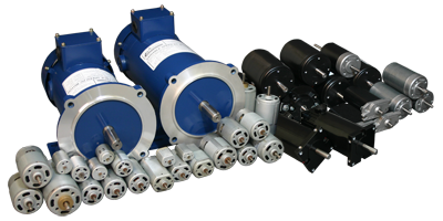
|
|
|
|
DC Motors
The Small Brush DC Motor is designed for high-volume OEM applications with low cost being the primary objective. The Small Brush DC Motor comes in sizes ranging from 0.29" to 3.6" in diameter. Anaheim Automation also offers a line of quality Permanent Magnet 56C DC Motors available in many different Horsepower levels, ranging from 1/2 all the way to 1 horsepower, with various operating voltages. Larger in size, these motors can deliver torque from 288 to 576 oz-in. Custom options include optimizing the maximum speed, torque, current, voltage, cabling, wiring, connectors, and shaft modifications. Our Brush DC Motors offer high quality at competitive prices. Please note that not all Small DC Motors are stock items, and that minimum purchases will be required for most part numbers listed. However, for most applications, going to another DC motor series, or just a size larger, may provide the solution for your requirements.
Brush Motor Selector
This utility will guide you in selecting the correct motor for your application!
- Torque: 0.3 to 18.5 Ounce-Inches
- Sizes: From 20mm to 52mm
- Cost-Effective Rotary Motion Control
- DC Motors are Fully Reversible
- Medical, Pump, Semiconductor Applications
- Popular for Robotics and Hobbyists
- Customization and Motor Adders Available
- Designed for High-Volume Applications (many items in stock for user customers)
- Torque: 8 to 190 Ounce-Inches
- Input Horsepower: From 1/27 to 1/3
- Voltage: 90VDC
- Sizes: From 66mm to 80mm
- Cost-Effective Rotary Motion Control
- DC Motors are Fully Reversible
- Double Shielded ball bearings
- Torque: 288 to 576 oz-in
- Frame Size: 56C
- Speed: 1800 and 2500 RPM
- Cost-Effective Rotary Motion Control
- DC Motors are Fully Reversible
- Totally enclosed fan cooled (TEFC)
- Class F Insulation Means Max Temp up to
221° F with Full Load
|
- DC Motors - History
- DC Motors - Basics
- DC Motors - Carbon Brushes
- DC Motors - Types
- DC Motors - Applications
- DC Motors - How Do Brush DC Motors Work
- DC Motors - Lifetime for Brush DC Motors
- DC Motors - Required Maintenance for Brush DC Motors
- Tech Tip Advantages and Disadvantages
- DC Motors - What are Brushed DC Motors
- DC Motors - What Industries are Brushed DC Motors Used In
- DC Motors - How Much Do Brush DC Motors Cost
- DC Motors
- DC Motors
.png)
The history of DC Motors can be traced back to the 1830's, when Michael Faraday set to devise an experiment to demonstrate whether or not a current carrying wire produced a circular magnetic field around it. Michael Faraday's experiment turned out to be a success; the current carrying wire did produce a circular magnetic field. While Michael Faraday is often credited for the invention of the electric Motors, his experiment is really just a lab demonstration; as you can't harness it for useful work. Several other scientists such as: Joseph Henry and William Sturgeon based their work on Faraday's experiment and theories and by the late nineteenth century the design of DC Motors had become well established. The demand for DC Motors has skyrocketed since than as a necessity in industrial applications.
The operation of all DC Motors is based on electromagnetism. DC Motors have two terminals, when voltage is applied across these two terminals of the DC Motors a proportional speed is outputted to the shaft of the DC Motors. Our DC Motors consists of two pieces; first we have the DC Motors stator which includes the housing, permanent magnets, and brushes and secondly we have the DC Motors rotor which consists of the output shaft, windings and commutator. The DC Motors stator is the stationary part of DC Motors and the DC Motors rotor rotates with respect to the DC Motors stator. When power is applied to the DC Motors rotor windings the polarity of the DC Motors windings and the DC Motors stator magnets are misaligned, and the DC Motors rotor will rotate until it is almost aligned with the stator magnets. As the DC Motors rotors reaches alignment, the brushes in the DC Motors move to the next commutator contacts and energize the next winding causing the current to reverse causing the winding and DC Motors stator magnets to misalign again, this process repeatedly is what keeps our DC Motors rotating.
In DC Motors a carbon brush is a device which conducts current between stationary wires and moving parts. For DC Motors to work, the coils of the DC Motors rotor must be connected to complete an actual circuit. To do this slip rings are affixed to the shaft of the DC Motors, and brushes attached to the rings which will be used to conduct the current. The carbon brush of DC Motors are a critical component of DC Motors but are considered the weak point in DC Motors as well because they are highly susceptible to wear especially when operating outside of operating parameters of the DC Motors. Although these carbon brushes of DC Motors are considered a weak point and can wear, they can also be easily replaced with new carbon brushes for the DC Motors. Although many people consider carbon brushes in DC Motors to be a "Black Art," they still serve a great purpose when subjected to the proper operating conditions. They tend to yield an excellent life and perform an amazing function for your DC Motors.
There are five basic DC motors; DC shunt mount motors, DC series wound motors, DC compound motors, DC permanent magnet motors, and DC separately excited motors. DC shunt wound motors will run at constant speed regardless of the load. With DC series wound motors the speed varies automatically with the load, increasing as the load decreases. This series wound motors are usually limited when heavy power demand is necessary. DC compound Motors are a combination of DC shunt and DC series wound motors by combining the characteristics of both. These DC compound motors are usually used when severe starting conditions are met and constant speed. DC Permanent magnet motors contain permanent magnets inside, hence the name, which eliminates the need for external field current. This design yields smaller, lighter, and energy efficient DC Motors. Lastly DC separately excited Motors are used for high torque capability at low speeds which is achieved by separately generating a high stator field current and enough armature voltage to produce the required rotor torque current.
Although DC Motors have been overshadowed by brushless motors, DC motors are still used in a wide range of applications. Just because we may not see DC motors very often, they really are everywhere ranging from toys to cellular phones to Jacuzzi pumps. Most automatic car windows and automatic seat adjustments are operated by DC motors. DC motors have been an automotive industry favorite because of their relatively low cost and simple design. DC motors come in all different sizes all with different torque and speed specifications; so whatever your application may be, there most likely are DC motors that will meet your demands.
Brush DC motors consist of two magnets facing the same direction, that surround two coils of wire that reside in the middle of DC motors around a rotor. The coils are positioned to face the magnets, causing electricity to flow to them. This generates a magnetic field, which ultimately pushes the coils away from the magnets they are facing, and causes the rotor to turn. The current shuts off at the rotor makes a 180 turn, causing each rotor to face the opposite magnet. As the current turns on again, the electricity flows oppositely, sending another pulse that causes the rotor to turn once again. The brushes that are located within DC motors transfer the electricity from the rotor, controlling the motors timing; turning it on and off when instructed.
The life of the brushes, bearings, and gearbox all play a role in the longevity of brush DC motors. Most commonly, life expectancies range from 2,000 to 5,000 hrs of operation, although actual service life varies. The design, operating current, speed, voltage, and other conditions of DC Motors are all contributing factors.
Always ensure the DC motors, as well as the motor environment is kept clean, preventing the motor from potentially encountering any type of dirt, oils, or debris. All mounting bolts should be kept tight, and the operation of the motor is in accordance with the given instructions on installation.
DC Motors generally tends to have increased maintenance requirements in comparison to those of AC motors, because many of the motors components are constantly coming in contact with one another. Over time, the brushes will wear and will require replacement. Also, the interaction between the commutator and the brushes will cause debris and contaminants to settle within DC motors, that require cleaning up after. Most commonly this occurs between the commutator and the shaft of DC motors, as well as between the winding and the armature.
Brushed DC Motors are one of the earliest of all electrical motor designs. It is usually the motor of choice for the majority of torque control and variable speed applications. This Tech Tip discusses the advantages and disadvantages of using Brushed DC motors in machinery and processes.
Advantages of Brushed DC Motors
• Brushed DC Motors have a simple construction, therefore requiring a cheap drive design
• Understandable design/technology facilitates in quick application of Brushed DC Motors.
• The design of Brushed DC motors are quite simple, in that a permanent magnetic field is created in the by either of two means:
• Permanent magnets
• Electro-magnetic windings
• If the field is created by permanent magnets, Brushed DC Motors are said to be a "permanent magnet DC motor" (PMDC). If created by electromagnetic windings, the brush motor is often said to be a "shunt wound Brush DC motor" (SWDC). Today, because of cost-effectiveness and reliability, the PMDC motor is the motor of choice for applications involving fractional horsepower brushed DC motors, as well as most applications up to about 2.0 horsepower.
• Opposing the stator field is the armature field, which is generated by a changing electromagnetic flux coming from windings located on the rotor of Brushed DC motors. The magnetic poles of the armature field will attempt to line up with the opposite magnetic poles generated by the stator field. Next, the section of the rotor where the electricity enters the rotor windings is called the commutator. The electricity is carried between the brush motor rotor and the stator by conductive graphite-copper brushes (mounted on the rotor) which contact rings on stator.
Important to Note: If Brushed DC motors suffer a loss of field (if for example, the field power connections are broken), the Brushed DC Motor will immediately begin to accelerate to the top speed which the loading will allow. This can result in the motor flying apart if the motor is lightly loaded. The possible loss of field must be accounted for, particularly with shunt wound Brushed DC Motors.
Imagine power is supplied:
Brushed DC Motors rotate toward the pole alignment point. Just as Brushed DC motors would get to this point, the brushes jump across a gap in the stator rings. Momentum carries brushed DC motors forward over this gap. When the brushes get to the other side of the gap, they contact the stator rings again and - the polarity of the voltage is reversed in this set of rings! The brush motor begins accelerating again, to the opposite set of poles. (The momentum has carried Brushed DC motors past the original pole alignment point.) This continues as Brushed DC Motors rotate. In most DC motors, several sets of windings or permanent magnets are present to smooth out the motion.
Brushed DC Motors are simple to control speed
• Simple to control speed - Controlling the speed of Brushed DC motors are simple. The higher the armature voltage, the faster the rotation. This relationship is linear to the brush motor's maximum speed.
• The maximum armature voltage which corresponds to the rated speed of the brush motors (these brush DC motors are usually given a rated speed and a maximum speed, such as 1750/2000 rpm) are available in certain standard voltages, which roughly increase in conjunction with horsepower.
• The smallest industrial-type brush DC motors are rated 90 VDC and 180 VDC. Larger units are rated at 250 VDC and even higher (dependent upon the individual manufacturer).
• Most industrial brush DC motors operate reliably over a speed range of about 20:1 - down to about 5-7% of base speed. This is much better performance than the comparable AC motor. This fact is in part due to the fact of the mere simplicity of control. However, it is also partly due to the fact that most industrial DC motors were designed with variable speed operations in mind. The addition of heat dissipation features/ devices provided for lower operating speeds of DC motors.
• NOTE: Specialty Brushed DC motors are used in mobile applications and are typically rated 12, 24, or 48 VDC. Other tiny brush motors can be rated as low as 5 VDC. These Brushed DC Motors are very popular among hobbyists.
Brushed DC Motors are simple to control torque
• In Brushed DC motors, torque control is also easy to accomplish. Output torque is proportional to current. So, if the current is limited, you have just limited the torque which brush DCmotors can achieve.
• This fact makes Brushed DC brushs motor ideal for delicate applications such as textile manufacturing.
Simple and inexpensive drive/control design
The result of this design is that variable speed or variable torque electronics are easy to design and manufacture. Varying the speed of Brushed DC motors requires little more than a large enough potentiometer. In practice, these have been replaced for all but sub-fractional horsepower applications by the SCR and PWM drives (sometimes referred to as controls), which offer relatively precisely control voltage and current. Common drives for a Brushed DC motor is available at the low-end of the product offering (up to 2 horsepower). The cost will depend on the accuracy requirement, but many brush motors can be accompanied with drives ranging from $29.00 - $199.00 USD.
Disadvantages of Brushed DC Motors
• Brushed DC motors can be a bit expensive to produce, in that the raw materials have become more costly in recent year
• Brushed DC motors are less reliable in control at lowest speeds
• Brushed DC motors are physically larger than other motors with the same torque
• Brushed DC motors are much more high maintenance than are brushless motors
• Brushed DC motors become vulnerable to dust which decrease
Brushed DC motors provide precision control of speed, driven by a direct current. Noted for a particularly high ratio of torque to inertia, brushed DC motors have the potential to supply three to four times more torque than its rated torque. If needed, it can even provide up to five times more than the rated torque, without stalling. Brushed DC motors consist of six different components: the axle, armature/rotor, commutator, stator, magnets, and brushes. Brushed DC motors offer stable and continuous current, using rings to power a magnetic drive that operates the motors armature. Perhaps one of the earliest used motors, brushed DC motors are commonly used because of the ability to vary the speed-torque ratio in almost any way.
Although the brushless DC motor has recently surpassed brushed DC motors because of its longetivity and reliability, brushed DC motors are still used in applications everywhere. Most commonly, brushed DC motors are found in household applications, but can also be found being used in the industrial world because of its versatility in altering its torque to speed ratio.
Brushed DC motors are particularly a favorite in the automotive industry, because of their simplicity and affordability. Many automotive manufacturers use them for power windows, seats, etc. However, brushed DC motors can be found in nearly every industry ranging from computer manufacturing to textiles to toys.
Brushed DC Motors has a relatively inexpensive and simple design. This is a major advantage to brush DC motors, in that its initial start-up costs are affordable; in some cases they are even half the price of their brushless counterparts. However due to the high maintenance and moderately short lifespan, brush DC motors tend to increase in price over time, because the brushes within DC motors are apt to wearing and require replacement.
Brushed DC motors provide precision control of speed, driven by a direct current. Noted for a particularly high ratio of torque to inertia, brushed DC motors have the potential to supply three to four times more torque than its rated torque. If needed, it can even provide up to five times more than the rated torque, without stalling. Brushed DC motors consist of six different components: the axle, armature/rotor, commutator, stator, magnets, and brushes. Brushed DC motors offer stable and continuous current, using rings to power a magnetic drive that operates the motors armature. Perhaps one of the earliest used motors, brushed DC motors are commonly used because of the ability to vary the speed-torque ratio in almost any way.
Although the brushless DC motor has recently surpassed brushed DC motors because of its longetivity and reliability, brushed DC motors are still used in applications everywhere. Most commonly, brushed DC motors are found in household applications, but can also be found being used in the industrial world because of its versatility in altering its torque to speed ratio.
Brushed DC motors are particularly a favorite in the automotive industry, because of their simplicity and affordability. Many automotive manufacturers use them for power windows, seats, etc. However, brushed DC motors can be found in nearly every industry ranging from computer manufacturing to textiles to toys.
The Direct Current Motor is one of the earliest of all electrical motor designs. It is usually the motor of choice for the majority of torque control and variable speed applications. This Tech Tip discusses the advantages and disadvantages of using a Direct Current Motor motor in machinery and processes.
Advantages of the Direct Current Motor
The Direct Current Motor has a simple construction, therefore requiring a cheap drive design
Understandable design/technology facilitates in quick application of a Motor.
The design of the Direct Current Motor is quite simple, in that a permanent magnetic field is created in the by either of two means:
Permanent magnets
Electro-magnetic windings
If the field is created by permanent magnets, a Brush DC Motor is said to be a permanent magnet DC motor (PMDC). If created by electromagnetic windings, the direct current motor is often said to be a shunt wound Brush DC motor (SWDC). Today, because of cost-effectiveness and reliability, the PMDC motor is the motor of choice for applications involving a fractional horsepower Direct Current Motor, as well as most applications up to about 2.0 horsepower.
Opposing the stator field is the armature field, which is generated by a changing electromagnetic flux coming from windings located on the rotor of the Direct Current Motor. The magnetic poles of the armature field will attempt to line up with the opposite magnetic poles generated by the stator field. Next, the section of the rotor where the electricity enters the rotor windings is called the commutator. The electricity is carried between the Direct Current Motor rotor and the stator by conductive graphite-copper brushes (mounted on the rotor) which contact rings on stator.
Important to Note: If a Brush DC motor suffers a loss of field (if for example, the field power connections are broken), the DC Motor will immediately begin to accelerate to the top speed which the loading will allow. This can result in the motor flying apart if the motor is lightly loaded. The possible loss of field must be accounted for, particularly with a shunt wound DC Motor.
Imagine power is supplied:
A Brush DC Motor rotates toward the pole alignment point. Just as the DC motor would get to this point, the brushes jump across a gap in the stator rings. Momentum carries the direct current motor forward over this gap. When the brushes get to the other side of the gap, they contact the stator rings again and - the polarity of the voltage is reversed in this set of rings! The direct current motor begins accelerating again, to the opposite set of poles. (The momentum has carried the direct current motor past the original pole alignment point.) This continues as the direct current motor rotates. In most DC motors, several sets of windings or permanent magnets are present to smooth out the motion.
THe Brush DC Motoor is simple to control speed
Simple to control speed - Controlling the speed of a DC motor is simple. The higher the armature voltage, the faster the rotation. This relationship is linear to the direct current motors maximum speed.
The maximum armature voltage which corresponds to the rated speed of the direct current motors (these direct current motors are usually given a rated speed and a maximum speed, such as 1750/2000 rpm) are available in certain standard voltages, which roughly increase in conjunction with horsepower.
The smallest industrial-type direct current motors are rated 90 VDC and 180 VDC. Larger units are rated at 250 VDC and even higher (dependent upon the individual manufacturer).
Most industrial DC direct current motors operate reliably over a speed range of about 20:1 - down to about 5-7% of base speed. This is much better performance than the comparable AC motor. This fact is in part due to the fact of the mere simplicity of control. However, it is also partly due to the fact that most industrial DC direct current motors were designed with variable speed operations in mind. The addition of heat dissipation features/ devices provided for lower operating speeds of DC direct current motors.
NOTE: The specialty DC motor is used in mobile applications and are typically rated 12, 24, or 48 VDC. Other tiny direct current motors can be rated as low as 5 VDC. This DC Motor is very popular among hobbyists.
The Brush DC Motor is simple to control torque
In a DC motor, torque control is also easy to accomplish. Output torque is proportional to current. So, if the current is limited, you have just limited the torque which the direct current motor can achieve.
This fact makes the DC direct current motor ideal for delicate applications such as textile manufacturing.
Simple and inexpensive drive/control design
The result of this design is that variable speed or variable torque electronics are easy to design and manufacture. Varying the speed of a DC motor requires little more than a large enough potentiometer. In practice, these have been replaced for all but sub-fractional horsepower applications by the SCR and PWM drives (sometimes referred to as controls), which offer relatively precisely control voltage and current. Common drives for a DC direct current motor is available at the low-end of the product offering (up to 2 horsepower). The cost will depend on the accuracy requirement, but many direct current motors can be accompanied with drives ranging from $29.00 - $199.00 USD.
Disadvantages of the Brush DC Motor
A Brush DC motor can be a bit expensive to produce, in that the raw materials have become more costly in recent year
A Brush DC motor is less reliable in control at lowest speeds
A Brush DC motor is physically larger than other motors with the same torque
A Brush DC motor is much more high maintenance than are brushless motors
A Brush DC motor becomes vulnerable to dust which decrease
Brushed Direct Current Motors are one of the earliest of all electrical motor designs. It is usually the motor of choice for the majority of torque control and variable speed applications. This Tech Tip discusses the advantages and disadvantages of using Brushed Direct Current motors in machinery and processes.
Advantages of Brushed Direct Current Motors
Brushed Direct Current Motors have a simple construction, therefore requiring a cheap drive design
Understandable design/technology facilitates in quick application of Brushed Direct Current Motors.
The design of Brushed Direct Current motors are quite simple, in that a permanent magnetic field is created in the by either of two means:
Permanent magnets
Electro-magnetic windings
If the field is created by permanent magnets, Brushed DC Motors are said to be a permanent magnet DC motor (PMDC). If created by electromagnetic windings, the brush motor is often said to be a shunt wound Brush DC motor (SWDC). Today, because of cost-effectiveness and reliability, the PMDC motor is the motor of choice for applications involving fractional horsepower brushed Direct Current motors, as well as most applications up to about 2.0 horsepower.
Opposing the stator field is the armature field, which is generated by a changing electromagnetic flux coming from windings located on the rotor of Brushed Direct Current motors. The magnetic poles of the armature field will attempt to line up with the opposite magnetic poles generated by the stator field. Next, the section of the rotor where the electricity enters the rotor windings is called the commutator. The electricity is carried between the brush motor rotor and the stator by conductive graphite-copper brushes (mounted on the rotor) which contact rings on stator.
Important to Note: If Brushed Direct Current motors suffer a loss of field (if for example, the field power connections are broken), the Brushed Direct Current Motor will immediately begin to accelerate to the top speed which the loading will allow. This can result in the motor flying apart if the motor is lightly loaded. The possible loss of field must be accounted for, particularly with shunt wound Brushed Direct Current Motors.
Imagine power is supplied:
Brushed Direct Current Motors rotate toward the pole alignment point. Just as Brushed Direct Current motors would get to this point, the brushes jump across a gap in the stator rings. Momentum carries brushed Direct Current motors forward over this gap. When the brushes get to the other side of the gap, they contact the stator rings again and - the polarity of the voltage is reversed in this set of rings! The brush motor begins accelerating again, to the opposite set of poles. (The momentum has carried Brushed Direct Current motors past the original pole alignment point.) This continues as Brushed DC Motors rotate. In most Direct Current motors, several sets of windings or permanent magnets are present to smooth out the motion.
Brushed Direct Current Motors are simple to control speed
Simple to control speed - Controlling the speed of Brushed Direct Current motors are simple. The higher the armature voltage, the faster the rotation. This relationship is linear to the brush motors maximum speed.
The maximum armature voltage which corresponds to the rated speed of the brush motors (these brush Direct Current motors are usually given a rated speed and a maximum speed, such as 1750/2000 rpm) are available in certain standard voltages, which roughly increase in conjunction with horsepower.
The smallest industrial-type brush Direct Current motors are rated 90 VDC and 180 VDC. Larger units are rated at 250 VDC and even higher (dependent upon the individual manufacturer).
Most industrial brush Direct Current motors operate reliably over a speed range of about 20:1 - down to about 5-7% of base speed. This is much better performance than the comparable AC motor. This fact is in part due to the fact of the mere simplicity of control. However, it is also partly due to the fact that most industrial DC motors were designed with variable speed operations in mind. The addition of heat dissipation features/ devices provided for lower operating speeds of Direct Current motors.
NOTE: Specialty Brushed Direct Current motors are used in mobile applications and are typically rated 12, 24, or 48 VDC. Other tiny brush motors can be rated as low as 5 VDC. These Brushed Direct Current Motors are very popular among hobbyists.
Brushed Direct Current Motors are simple to control torque
In Brushed Direct Current motors, torque control is also easy to accomplish. Output torque is proportional to current. So, if the current is limited, you have just limited the torque which brush Direct Current can achieve.
This fact makes Brushed Direct Current brushs motor ideal for delicate applications such as textile manufacturing.
Simple and inexpensive drive/control design
The result of this design is that variable speed or variable torque electronics are easy to design and manufacture. Varying the speed of Brushed Direct Current motors requires little more than a large enough potentiometer. In practice, these have been replaced for all but sub-fractional horsepower applications by the SCR and PWM drives (sometimes referred to as controls), which offer relatively precisely control voltage and current. Common drives for a Brushed Direct Current motor is available at the low-end of the product offering (up to 2 horsepower). The cost will depend on the accuracy requirement, but many brush motors can be accompanied with drives ranging from $29.00 - $199.00 USD.
Disadvantages of Brushed Direct Current Motors
Brushed Direct Current motors can be a bit expensive to produce, in that the raw materials have become more costly in recent year
Brushed Direct Current motors are less reliable in control at lowest speeds
Brushed Direct Current motors are physically larger than other motors with the same torque
Brushed Direct Current motors are much more high maintenance than are brushless motors
Brushed Direct Current motors become vulnerable to dust which decrease
Although the permanenet magnetless DC motor has recently surpassed Permanenet Magnet motors because of its longetivity and reliability, permanenet magneted DC motors are still used in applications everywhere. Most commonly, Permanenet Magnet motors are found in household applications, but can also be found being used in the industrial world because of its versatility in altering its torque to speed ratio.
Permanenet Magnet motors are particularly a favorite in the automotive industry, because of their simplicity and affordability. Many automotive manufacturers use them for power windows, seats, etc. However, permanenet magneted Permanenet Magnet motors can be found in nearly every industry ranging from computer manufacturing to textiles to toys.
The Permanent Magnet DC Motor is one of the earliest of all electrical motor designs. It is usually the motor of choice for the majority of torque control and variable speed applications. This Tech Tip discusses the advantages and disadvantages of using a Permanent Magnet DC Brush motor in machinery and processes.
Advantages of the Permanent Magnet DC Motor
The Permanent Magnet DC Motor has a simple construction, therefore requiring a cheap drive design
Understandable design/technology facilitates in quick application of a Permanent Magnet DC Motor.
The design of the Permanent Magnet DC motor is quite simple, in that a permanent magnetic field is created in the by either of two means:
Permanent magnets
Electro-magnetic windings
If the field is created by permanent magnets, a Permanent Magnet DC Motor is said to be a permanent magnet DC motor (PMDC). If created by electromagnetic windings, the brush motor is often said to be a shunt wound Brush DC motor (SWDC). Today, because of cost-effectiveness and reliability, the PMDC motor is the motor of choice for applications involving fractional horsepower DC permanent magnet motors, as well as most applications up to about 2.0 horsepower.
Opposing the stator field is the armature field, which is generated by a changing electromagnetic flux coming from windings located on the rotor of the Permanent Magnet DC motor. The magnetic poles of the armature field will attempt to line up with the opposite magnetic poles generated by the stator field. Next, the section of the rotor where the electricity enters the rotor windings is called the commutator. The electricity is carried between the brush motor rotor and the stator by conductive graphite-copper brushes (mounted on the rotor) which contact rings on stator.
Important to Note: If a Permanent Magnet DC motor suffers a loss of field (if for example, the field power connections are broken), the Permanent Magnet DC Motor will immediately begin to accelerate to the top speed which the loading will allow. This can result in the motor flying apart if the motor is lightly loaded. The possible loss of field must be accounted for, particularly with a shunt wound Permanent Magnet DC Motor.
Imagine power is supplied:
A Permanent Magnet DC Motor rotates toward the pole alignment point. Just as the Permanent Magnet DC motor would get to this point, the brushes jump across a gap in the stator rings. Momentum carries the permanent magnet DC motor forward over this gap. When the brushes get to the other side of the gap, they contact the stator rings again and - the polarity of the voltage is reversed in this set of rings! The brush motor begins accelerating again, to the opposite set of poles. (The momentum has carried the Permanent Magnet DC motor past the original pole alignment point.) This continues as the Permanent Magnet DC Motor rotates. In most DC motors, several sets of windings or permanent magnets are present to smooth out the motion.
The Permanent Magnet DC Motor is simple to control speed
Simple to control speed - Controlling the speed of a Permanent Magnet DC motor is simple. The higher the armature voltage, the faster the rotation. This relationship is linear to the brush motors maximum speed.
The maximum armature voltage which corresponds to the rated speed of the brush motors (these brush motors are usually given a rated speed and a maximum speed, such as 1750/2000 rpm) are available in certain standard voltages, which roughly increase in conjunction with horsepower.
The smallest industrial-type brush motors are rated 90 VDC and 180 VDC. Larger units are rated at 250 VDC and even higher (dependent upon the individual manufacturer).
Most industrial DC brush motors operate reliably over a speed range of about 20:1 - down to about 5-7% of base speed. This is much better performance than the comparable AC motor. This fact is in part due to the fact of the mere simplicity of control. However, it is also partly due to the fact that most industrial DC brush motors were designed with variable speed operations in mind. The addition of heat dissipation features/ devices provided for lower operating speeds of DC brush motors.
NOTE: The specialty Permanent Magnet DC motor is used in mobile applications and are typically rated 12, 24, or 48 VDC. Other tiny brush motors can be rated as low as 5 VDC. This Permanent Magnet DC Motor is very popular among hobbyists.
The Permanent Magnet DC Motor is simple to control torque
In a Permanent Magnet DC motor, torque control is also easy to accomplish. Output torque is proportional to current. So, if the current is limited, you have just limited the torque which the brush motor can achieve.
This fact makes the Permanent Magnet DC brush motor ideal for delicate applications such as textile manufacturing.
Simple and inexpensive drive/control design
The result of this design is that variable speed or variable torque electronics are easy to design and manufacture. Varying the speed of a Permanent Magnet DC motor requires little more than a large enough potentiometer. In practice, these have been replaced for all but sub-fractional horsepower applications by the SCR and PWM drives (sometimes referred to as controls), which offer relatively precisely control voltage and current. Common drives for a Permanent Magnet DC motor is available at the low-end of the product offering (up to 2 horsepower). The cost will depend on the accuracy requirement, but many brush motors can be accompanied with drives ranging from $29.00 - $199.00 USD.
Disadvantages of the Permanent Magnet DC Motor
A Permanent Magnet DC motor can be a bit expensive to produce, in that the raw materials have become more costly in recent year
A Permanent Magnet DC motor is less reliable in control at lowest speeds
A Permanent Magnet DC motor is physically larger than other motors with the same torque
A Permanent Magnet DC motor is much more high maintenance than are brushless motors
A Permanent Magnet DC motor becomes vulnerable to dust which decrease
Although Permanent Magnet DC Motors have been overshadowed by the brushless motor, Permanent Magnet DC Motors are still used in a wide range of applications. Just because we may not see Permanent Magnet DC Motors very often, they really are everywhere ranging from toys to cellular phones to Jacuzzi pumps. Most automatic car windows and automatic seat adjustments are operated by Brush Motors. Permanent Magnet DC Motors have been an automotive industry favorite because of their relatively low cost and simple design. Permanent Magnet DC Motors come in all different sizes all with different torque and speed specifications; so whatever your application may be there most likely are Permanent Magnet DC Motors that will meet your demands.
The operation of any Permanent Magnet DC Motors are based on electromagnetism. The Permanent Magnet DC Motors have two terminals, when voltage is applied across these two terminals of the Permanent Magnet DC Motors, a proportional speed is outputted to the shaft of Permanent Magnet DC Motors. Our Permanent Magnet DC Motors consist of two pieces; first we have the Permanent Magnet DC Motor stator which includes the housing, permanent magnets, and brushes and secondly we have the Permanent Magnet DC Motor rotor which consists of the output shaft, windings and commutator. The Permanent Magnet DC Motor stator is the stationary part of the Brush Motor and the Permanent Magnet DC Motor rotor rotates with respect to the Brush Motor stator. When power is applied to the Permanent Magnet DC Motor rotor windings the polarity of the winding and stator magnets are misaligned, and the Permanent Magnet DC Motor rotor will rotate until it is almost aligned with the stator magnets. As the Permanent Magnet DC Motor rotors reaches alignment, the brushes in Permanent Magnet DC Motors move to the next commutator contacts and energize the next winding causing the current to reverse causing the winding and Brush Motor stator magnets to misalign again, this process repeatedly is what keeps our Permanent Magnet DC Motors rotating.
In Permanent Magnet DC Motors, a carbon brush is a device which conducts current between stationary wires and moving parts. For DC Motors to work, the coils of the Permanent Magnet DC Motor rotor must be connected to complete an actual circuit. To do this, slip rings are affixed to the shaft of Permanent Magnet DC Motors, and brushes attached to the rings which will be used to conduct the current. The carbon brush of Permanent Magnet DC Motors is a critical component of DC Motors but is considered the weak point in the DC Motors as well because it is highly susceptible to wear, especially when operating outside of operating parameters of the Permanent Magnet DC Motors. Although these carbon brushes of Permanent Magnet DC Motors are considered a weak point and can wear, they can also be easily replaced with new carbon brushes for Permanent Magnet DC Motors. Although many people consider carbon brushes in Permanent Magnet DC Motors to be a Black Art, they still serve a great purpose when subjected to the proper operating conditions. They tend to yield an excellent life and perform an amazing function for Permanent Magnet DC Motors.
The history of Permanent Magnet DC Motors can be traced back to the 1830s, when Michael Faraday set to devise an experiment to demonstrate whether or not a current carrying wire produced a circular magnetic field around it. Michael Faradays experiment turned out to be a success; the current carrying wire did produce a circular magnetic field. While Michael Faraday is often credited for the invention of the electric motor, his experiment is really just a lab demonstration; as you cant harness it for useful work. Several other scientists such as: Joseph Henry and William Sturgeon based their work on Faradays experiment and theories and by the late nineteenth century the design of Permanent Magnet DC Motors had become well established. The demand for Permanent Magnet DC Motors has skyrocketed since than as a necessity in industrial applications.
Permanent Magnet DC motors consist of two magnets facing the same direction, that surround two coils of wire that reside in the middle of Permanent Magnet DC motors around a rotor. The coils are positioned to face the magnets, causing electricity to flow to them. This generates a magnetic field, which ultimately pushes the coils away from the magnets they are facing, and causes the rotor to turn. The current shuts off at the rotor makes a 180 turn, causing each rotor to face the opposite magnet. As the current turns on again, the electricity flows oppositely, sending another pulse that causes the rotor to turn once again. The brushes that are located within Permanent Magnet DC motors transfer the electricity from the rotor, controlling the motors timing; turning it on and off when instructed.
Permanent Magnet DC Motors have a relatively inexpensive and simple design. This is a major advantage to the permanent magnet DC motors, in that their initial start-up costs are affordable; in some cases they are even half the price of their brushless counterparts. However due to the high maintenance and moderately short lifespan, permanent magnet DC motors tend to increase in price over time, because the brushes within Permanent Magnet DC Motors are apt to wearing and require replacement.
The life of the brushes, bearings, and gearbox all play a role in the longevity of permanent magnet DC motors. Most commonly, life expectancies range from 2,000 to 5,000 hrs of operation, although actual service life varies. The design, operating current, speed, voltage, and other conditions of Permanent Magnet DC Motors are all contributing factors.
Always ensure the Permanent Magnet DC motors, as well as the motor environment is kept clean, preventing the motor from potentially encountering any type of dirt, oils, or debris. All mounting bolts should be kept tight, and the operation of the motor is in accordance with the given instructions on installation.
Permanent Magnet DC Motors generally tends to have increased maintenance requirements in comparison to those of AC motors, because many of the motors components are constantly coming in contact with one another. Over time, the brushes will wear and will require replacement. Also, the interaction between the commutator and the brushes will cause debris and contaminants to settle within Permanent Magnet DC motors, that require cleaning up after. Most commonly this occurs between the commutator and the shaft of Permanent Magnet DC motors, as well as between the winding and the armature.
Permanent Magnet DC Motors are one of the earliest of all electrical motor designs. It is usually the motor of choice for the majority of torque control and variable speed applications. This Tech Tip discusses the advantages and disadvantages of using Permanent Magnet DC motors in machinery and processes.
Advantages of Permanent Magnet DC Motors
Permanent Magnet DC Motors have a simple construction, therefore requiring a cheap drive design
Understandable design/technology facilitates in quick application of Permanent Magnet DC Motors.
The design of Permanent Magnet DC motors are quite simple, in that a permanent magnetic field is created in the by either of two means:
Permanent magnets
Electro-magnetic windings
If the field is created by permanent magnets, Permanent Magnet DC Motors are said to be a permanent magnet DC motor (PMDC). If created by electromagnetic windings, the brush motor is often said to be a shunt wound Brush DC motor (SWDC). Today, because of cost-effectiveness and reliability, the PMDC motor is the motor of choice for applications involving fractional horsepower permanent magnet DC motors, as well as most applications up to about 2.0 horsepower.
Opposing the stator field is the armature field, which is generated by a changing electromagnetic flux coming from windings located on the rotor of Permanent Magnet DC motors. The magnetic poles of the armature field will attempt to line up with the opposite magnetic poles generated by the stator field. Next, the section of the rotor where the electricity enters the rotor windings is called the commutator. The electricity is carried between the brush motor rotor and the stator by conductive graphite-copper brushes (mounted on the rotor) which contact rings on stator.
Important to Note: If Permanent Magnet DC motors suffer a loss of field (if for example, the field power connections are broken), the Permanent Magnet DC Motor will immediately begin to accelerate to the top speed which the loading will allow. This can result in the motor flying apart if the motor is lightly loaded. The possible loss of field must be accounted for, particularly with shunt wound Permanent Magnet DC Motors.
Imagine power is supplied:
Permanent Magnet DC Motors rotate toward the pole alignment point. Just as Permanent Magnet DC motors would get to this point, the brushes jump across a gap in the stator rings. Momentum carries permanent magnet DC motors forward over this gap. When the brushes get to the other side of the gap, they contact the stator rings again and - the polarity of the voltage is reversed in this set of rings! The brush motor begins accelerating again, to the opposite set of poles. (The momentum has carried Permanent Magnet DC motors past the original pole alignment point.) This continues as Permanent Magnet DC Motors rotate. In most DC motors, several sets of windings or permanent magnets are present to smooth out the motion.
Permanent Magnet DC Motors are simple to control speed
Simple to control speed - Controlling the speed of Permanent Magnet DC motors are simple. The higher the armature voltage, the faster the rotation. This relationship is linear to the brush motors maximum speed.
The maximum armature voltage which corresponds to the rated speed of the brush motors (these brush DC motors are usually given a rated speed and a maximum speed, such as 1750/2000 rpm) are available in certain standard voltages, which roughly increase in conjunction with horsepower.
The smallest industrial-type brush DC motors are rated 90 VDC and 180 VDC. Larger units are rated at 250 VDC and even higher (dependent upon the individual manufacturer).
Most industrial brush DC motors operate reliably over a speed range of about 20:1 - down to about 5-7% of base speed. This is much better performance than the comparable AC motor. This fact is in part due to the fact of the mere simplicity of control. However, it is also partly due to the fact that most industrial DC motors were designed with variable speed operations in mind. The addition of heat dissipation features/ devices provided for lower operating speeds of DC motors.
NOTE: Specialty Permanent Magnet DC motors are used in mobile applications and are typically rated 12, 24, or 48 VDC. Other tiny brush motors can be rated as low as 5 VDC. These Permanent Magnet DC Motors are very popular among hobbyists.
Permanent Magnet DC Motors are simple to control torque
In Permanent Magnet DC motors, torque control is also easy to accomplish. Output torque is proportional to current. So, if the current is limited, you have just limited the torque which brush DCmotors can achieve.
This fact makes Permanent Magnet DC brushs motor ideal for delicate applications such as textile manufacturing.
Simple and inexpensive drive/control design
The result of this design is that variable speed or variable torque electronics are easy to design and manufacture. Varying the speed of Permanent Magnet DC motors requires little more than a large enough potentiometer. In practice, these have been replaced for all but sub-fractional horsepower applications by the SCR and PWM drives (sometimes referred to as controls), which offer relatively precisely control voltage and current. Common drives for a Permanent Magnet DC motor is available at the low-end of the product offering (up to 2 horsepower). The cost will depend on the accuracy requirement, but many brush motors can be accompanied with drives ranging from $29.00 - $199.00 USD.
Disadvantages of Permanent Magnet DC Motors
Permanent Magnet DC motors can be a bit expensive to produce, in that the raw materials have become more costly in recent year
Permanent Magnet DC motors are less reliable in control at lowest speeds
Permanent Magnet DC motors are physically larger than other motors with the same torque
Permanent Magnet DC motors are much more high maintenance than are brushless motors
Permanent Magnet DC motors become vulnerable to dust which decrease
There are five basic types of Permanent Magnet DC Motors: permanent magnet shunt mount motor, permanent magnet series wound motor, permanent magnet compound motor, permanent magnet permanent magnet motor, and permanent magnet separately excited Permanent Magnet DC motor. A permanent magnet shunt wound motor will run at constant speed regardless of the load. With series wound Permanent Magnet DC motors the speed varies automatically with the load, increasing as the load decreases. This series wound motor is usually limited when heavy power demand is necessary. The compound Permanent Magnet DC motors are a combination of the permanent magnet shunt and permanent magnet series wound motors by combining the characteristics of both. Compound Permanent Magnet DC motors are usually used when severe starting conditions are met and constant speed. Permanent Magnet Permanent magnet motors contain permanent magnets inside, hence the name, which eliminates the need for external field current. This design yields a smaller, lighter, and energy efficient Permanent Magnet DC Motors. Lastly the permanent magnet separately excited motor is used for its high torque capability at low speeds which is achieved by separately generating a high stator field current and enough armature voltage to produce the required rotor torque current.
Permanent Magnet DC motors provide precision control of speed, driven by a direct current. Noted for a particularly high ratio of torque to inertia, permanent magnet DC motors have the potential to supply three to four times more torque than its rated torque. If needed, it can even provide up to five times more than the rated torque, without stalling. Permanent Magnet DC motors consist of six different components: the axle, armature/rotor, commutator, stator, magnets, and brushes. Permanent Magnet DC motors offer stable and continuous current, using rings to power a magnetic drive that operates the motors armature. Perhaps one of the earliest used motors, permanent magnet DC motors are commonly used because of the ability to vary the speed-torque ratio in almost any way.
Although the brushless DC motor has recently surpassed permanent magnet DC motors because of its longetivity and reliability, permanent magnet DC motors are still used in applications everywhere. Most commonly, permanent magnet DC motors are found in household applications, but can also be found being used in the industrial world because of its versatility in altering its torque to speed ratio.
Permanent Magnet DC motors are particularly a favorite in the automotive industry, because of their simplicity and affordability. Many automotive manufacturers use them for power windows, seats, etc. However, permanent magnet DC motors can be found in nearly every industry ranging from computer manufacturing to textiles to toys.
The Permanent Magnet Motor is one of the earliest of all electrical motor designs. It is usually the motor of choice for the majority of torque control and variable speed applications. This Tech Tip discusses the advantages and disadvantages of using a Permanent Magnet Motor motor in machinery and processes.
Advantages of the Permanent Magnet Motor
The Permanent Magnet Motor has a simple construction, therefore requiring a cheap drive design
Understandable design/technology facilitates in quick application of a Motor.
The design of the Permanent Magnet Motor is quite simple, in that a permanent magnetic field is created in the by either of two means:
Permanent magnets
Electro-magnetic windings
If the field is created by permanent magnets, a Permanent Magnet DC Motor is said to be a permanent magnet DC motor (PMDC). If created by electromagnetic windings, the permanent magnet motor is often said to be a shunt wound Permanent Magnet DC motor (SWDC). Today, because of cost-effectiveness and reliability, the PMDC motor is the motor of choice for applications involving a fractional horsepower Permanent Magnet Motor, as well as most applications up to about 2.0 horsepower.
Opposing the stator field is the armature field, which is generated by a changing electromagnetic flux coming from windings located on the rotor of the Permanent Magnet Motor. The magnetic poles of the armature field will attempt to line up with the opposite magnetic poles generated by the stator field. Next, the section of the rotor where the electricity enters the rotor windings is called the commutator. The electricity is carried between the Permanent Magnet Motor rotor and the stator by conductive graphite-copper brushes (mounted on the rotor) which contact rings on stator.
Important to Note: If a Permanent Magnet DC motor suffers a loss of field (if for example, the field power connections are broken), the DC Motor will immediately begin to accelerate to the top speed which the loading will allow. This can result in the motor flying apart if the motor is lightly loaded. The possible loss of field must be accounted for, particularly with a shunt wound DC Motor.
Imagine power is supplied:
A Permanent Magnet DC Motor rotates toward the pole alignment point. Just as the DC motor would get to this point, the brushes jump across a gap in the stator rings. Momentum carries the permanent magnet motor forward over this gap. When the brushes get to the other side of the gap, they contact the stator rings again and - the polarity of the voltage is reversed in this set of rings! The permanent magnet motor begins accelerating again, to the opposite set of poles. (The momentum has carried the permanent magnet motor past the original pole alignment point.) This continues as the permanent magnet motor rotates. In most DC motors, several sets of windings or permanent magnets are present to smooth out the motion.
THe Permanent Magnet DC Motoor is simple to control speed
Simple to control speed - Controlling the speed of a DC motor is simple. The higher the armature voltage, the faster the rotation. This relationship is linear to the permanent magnet motors maximum speed.
The maximum armature voltage which corresponds to the rated speed of the permanent magnet motors (these permanent magnet motors are usually given a rated speed and a maximum speed, such as 1750/2000 rpm) are available in certain standard voltages, which roughly increase in conjunction with horsepower.
The smallest industrial-type permanent magnet motors are rated 90 VDC and 180 VDC. Larger units are rated at 250 VDC and even higher (dependent upon the individual manufacturer).
Most industrial DC permanent magnet motors operate reliably over a speed range of about 20:1 - down to about 5-7% of base speed. This is much better performance than the comparable AC motor. This fact is in part due to the fact of the mere simplicity of control. However, it is also partly due to the fact that most industrial DC permanent magnet motors were designed with variable speed operations in mind. The addition of heat dissipation features/ devices provided for lower operating speeds of DC permanent magnet motors.
NOTE: The specialty DC motor is used in mobile applications and are typically rated 12, 24, or 48 VDC. Other tiny permanent magnet motors can be rated as low as 5 VDC. This DC Motor is very popular among hobbyists.
The Permanent Magnet DC Motor is simple to control torque
In a DC motor, torque control is also easy to accomplish. Output torque is proportional to current. So, if the current is limited, you have just limited the torque which the permanent magnet motor can achieve.
This fact makes the DC permanent magnet motor ideal for delicate applications such as textile manufacturing.
Simple and inexpensive drive/control design
The result of this design is that variable speed or variable torque electronics are easy to design and manufacture. Varying the speed of a DC motor requires little more than a large enough potentiometer. In practice, these have been replaced for all but sub-fractional horsepower applications by the SCR and PWM drives (sometimes referred to as controls), which offer relatively precisely control voltage and current. Common drives for a DC permanent magnet motor is available at the low-end of the product offering (up to 2 horsepower). The cost will depend on the accuracy requirement, but many permanent magnet motors can be accompanied with drives ranging from $29.00 - $199.00 USD.
Disadvantages of the Permanent Magnet DC Motor
A Permanent Magnet DC motor can be a bit expensive to produce, in that the raw materials have become more costly in recent year
A Permanent Magnet DC motor is less reliable in control at lowest speeds
A Permanent Magnet DC motor is physically larger than other motors with the same torque
A Permanent Magnet DC motor is much more high maintenance than are brushless motors
A Permanent Magnet DC motor becomes vulnerable to dust which decrease
The Permanent Magnetic Motor is one of the earliest of all electrical motor designs. It is usually the motor of choice for the majority of torque control and variable speed applications. This Tech Tip discusses the advantages and disadvantages of using a Permanent Magnetic Motor motor in machinery and processes.
Advantages of the Permanent Magnetic Motor
The Permanent Magnetic Motor has a simple construction, therefore requiring a cheap drive design
Understandable design/technology facilitates in quick application of a Motor.
The design of the Permanent Magnetic Motor is quite simple, in that a permanent magnetic field is created in the by either of two means:
Permanent magnets
Electro-magnetic windings
If the field is created by permanent magnets, a Permanent Magnetic DC Motor is said to be a permanent magnetic DC motor (PMDC). If created by electromagnetic windings, the permanent magnetic motor is often said to be a shunt wound Permanent Magnetic DC motor (SWDC). Today, because of cost-effectiveness and reliability, the PMDC motor is the motor of choice for applications involving a fractional horsepower Permanent Magnetic Motor, as well as most applications up to about 2.0 horsepower.
Opposing the stator field is the armature field, which is generated by a changing electromagnetic flux coming from windings located on the rotor of the Permanent Magnetic Motor. The magnetic poles of the armature field will attempt to line up with the opposite magnetic poles generated by the stator field. Next, the section of the rotor where the electricity enters the rotor windings is called the commutator. The electricity is carried between the Permanent Magnetic Motor rotor and the stator by conductive graphite-copper brushes (mounted on the rotor) which contact rings on stator.
Important to Note: If a Permanent Magnetic DC motor suffers a loss of field (if for example, the field power connections are broken), the DC Motor will immediately begin to accelerate to the top speed which the loading will allow. This can result in the motor flying apart if the motor is lightly loaded. The possible loss of field must be accounted for, particularly with a shunt wound DC Motor.
Imagine power is supplied:
A Permanent Magnetic DC Motor rotates toward the pole alignment point. Just as the DC motor would get to this point, the brushes jump across a gap in the stator rings. Momentum carries the permanent magnetic motor forward over this gap. When the brushes get to the other side of the gap, they contact the stator rings again and - the polarity of the voltage is reversed in this set of rings! The permanent magnetic motor begins accelerating again, to the opposite set of poles. (The momentum has carried the permanent magnetic motor past the original pole alignment point.) This continues as the permanent magnetic motor rotates. In most DC motors, several sets of windings or permanent magnets are present to smooth out the motion.
THe Permanent Magnetic DC Motoor is simple to control speed
Simple to control speed - Controlling the speed of a DC motor is simple. The higher the armature voltage, the faster the rotation. This relationship is linear to the permanent magnetic motors maximum speed.
The maximum armature voltage which corresponds to the rated speed of the permanent magnetic motors (these permanent magnetic motors are usually given a rated speed and a maximum speed, such as 1750/2000 rpm) are available in certain standard voltages, which roughly increase in conjunction with horsepower.
The smallest industrial-type permanent magnetic motors are rated 90 VDC and 180 VDC. Larger units are rated at 250 VDC and even higher (dependent upon the individual manufacturer).
Most industrial DC permanent magnetic motors operate reliably over a speed range of about 20:1 - down to about 5-7% of base speed. This is much better performance than the comparable AC motor. This fact is in part due to the fact of the mere simplicity of control. However, it is also partly due to the fact that most industrial DC permanent magnetic motors were designed with variable speed operations in mind. The addition of heat dissipation features/ devices provided for lower operating speeds of DC permanent magnetic motors.
NOTE: The specialty DC motor is used in mobile applications and are typically rated 12, 24, or 48 VDC. Other tiny permanent magnetic motors can be rated as low as 5 VDC. This DC Motor is very popular among hobbyists.
The Permanent Magnetic DC Motor is simple to control torque
In a DC motor, torque control is also easy to accomplish. Output torque is proportional to current. So, if the current is limited, you have just limited the torque which the permanent magnetic motor can achieve.
This fact makes the DC permanent magnetic motor ideal for delicate applications such as textile manufacturing.
Simple and inexpensive drive/control design
The result of this design is that variable speed or variable torque electronics are easy to design and manufacture. Varying the speed of a DC motor requires little more than a large enough potentiometer. In practice, these have been replaced for all but sub-fractional horsepower applications by the SCR and PWM drives (sometimes referred to as controls), which offer relatively precisely control voltage and current. Common drives for a DC permanent magnetic motor is available at the low-end of the product offering (up to 2 horsepower). The cost will depend on the accuracy requirement, but many permanent magnetic motors can be accompanied with drives ranging from $29.00 - $199.00 USD.
Disadvantages of the Permanent Magnetic DC Motor
A Permanent Magnetic DC motor can be a bit expensive to produce, in that the raw materials have become more costly in recent year
A Permanent Magnetic DC motor is less reliable in control at lowest speeds
A Permanent Magnetic DC motor is physically larger than other motors with the same torque
A Permanent Magnetic DC motor is much more high maintenance than are brushless motors
A Permanent Magnetic DC motor becomes vulnerable to dust which decrease
The PMDC Motor is one of the earliest of all electrical motor designs. It is usually the motor of choice for the majority of torque control and variable speed applications. This Tech Tip discusses the advantages and disadvantages of using a PMDC Brush motor in machinery and processes.
Advantages of the PMDC Motor
The Brush PMDC Motor has a simple construction, therefore requiring a cheap drive design
Understandable design/technology facilitates in quick application of a PMDC Motor.
The design of the PMDC motor is quite simple, in that a permanent magnetic field is created in the by either of two means:
Permanent magnets
Electro-magnetic windings
If the field is created by permanent magnets, a Brush PMDC Motor is said to be a permanent magnet PMDC motor (PMPMDC). If created by electromagnetic windings, the brush motor is often said to be a shunt wound Brush PMDC motor (SWPMDC). Today, because of cost-effectiveness and reliability, the PMPMDC motor is the motor of choice for applications involving fractional horsepower PMDC brush motors, as well as most applications up to about 2.0 horsepower.
Opposing the stator field is the armature field, which is generated by a changing electromagnetic flux coming from windings located on the rotor of the Brush PMDC motor. The magnetic poles of the armature field will attempt to line up with the opposite magnetic poles generated by the stator field. Next, the section of the rotor where the electricity enters the rotor windings is called the commutator. The electricity is carried between the brush motor rotor and the stator by conductive graphite-copper brushes (mounted on the rotor) which contact rings on stator.
Important to Note: If a Brush PMDC motor suffers a loss of field (if for example, the field power connections are broken), the PMDC Motor will immediately begin to accelerate to the top speed which the loading will allow. This can result in the motor flying apart if the motor is lightly loaded. The possible loss of field must be accounted for, particularly with a shunt wound PMDC Motor.
Imagine power is supplied:
A Brush PMDC Motor rotates toward the pole alignment point. Just as the PMDC motor would get to this point, the brushes jump across a gap in the stator rings. Momentum carries the brush motor forward over this gap. When the brushes get to the other side of the gap, they contact the stator rings again and - the polarity of the voltage is reversed in this set of rings! The brush motor begins accelerating again, to the opposite set of poles. (The momentum has carried the brush motor past the original pole alignment point.) This continues as the brush motor rotates. In most PMDC motors, several sets of windings or permanent magnets are present to smooth out the motion.
Te Brush PMDC Motor is simple to control speed
Simple to control speed - Controlling the speed of a PMDC motor is simple. The higher the armature voltage, the faster the rotation. This relationship is linear to the brush motors maximum speed.
The maximum armature voltage which corresponds to the rated speed of the brush motors (these brush motors are usually given a rated speed and a maximum speed, such as 1750/2000 rpm) are available in certain standard voltages, which roughly increase in conjunction with horsepower.
The smallest industrial-type brush motors are rated 90 VPMDC and 180 VPMDC. Larger units are rated at 250 VPMDC and even higher (dependent upon the individual manufacturer).
Most industrial PMDC brush motors operate reliably over a speed range of about 20:1 - down to about 5-7% of base speed. This is much better performance than the comparable AC motor. This fact is in part due to the fact of the mere simplicity of control. However, it is also partly due to the fact that most industrial PMDC brush motors were designed with variable speed operations in mind. The addition of heat dissipation features/ devices provided for lower operating speeds of PMDC brush motors.
NOTE: The specialty PMDC motor is used in mobile applications and are typically rated 12, 24, or 48 VPMDC. Other tiny brush motors can be rated as low as 5 VPMDC. This PMDC Motor is very popular among hobbyists.
The Brush PMDC Motor is simple to control torque
In a PMDC motor, torque control is also easy to accomplish. Output torque is proportional to current. So, if the current is limited, you have just limited the torque which the brush motor can achieve.
This fact makes the PMDC brush motor ideal for delicate applications such as textile manufacturing.
Simple and inexpensive drive/control design
The result of this design is that variable speed or variable torque electronics are easy to design and manufacture. Varying the speed of a PMDC motor requires little more than a large enough potentiometer. In practice, these have been replaced for all but sub-fractional horsepower applications by the SCR and PWM drives (sometimes referred to as controls), which offer relatively precisely control voltage and current. Common drives for a PMDC brush motor is available at the low-end of the product offering (up to 2 horsepower). The cost will depend on the accuracy requirement, but many brush motors can be accompanied with drives ranging from $29.00 - $199.00 USD.
Disadvantages of the Brush PMDC Motor
A Brush PMDC motor can be a bit expensive to produce, in that the raw materials have become more costly in recent year
A Brush PMDC motor is less reliable in control at lowest speeds
A Brush PMDC motor is physically larger than other motors with the same torque
A Brush PMDC motor is much more high maintenance than are brushless motors
A Brush PMDC motor becomes vulnerable to dust which decrease
Although Brush PMDC Motors have been overshadowed by the brushless motor, Brush PMDC Motors are still used in a wide range of applications. Just because we may not see Brush Motors very often, they really are everywhere ranging from toys to cellular phones to Jacuzzi pumps. Most automatic car windows and automatic seat adjustments are operated by Brush Motors. Brush PMDC Motors have been an automotive industry favorite because of their relatively low cost and simple design. Brush PMDC Motors come in all different sizes all with different torque and speed specifications; so whatever your application may be there most likely are Brush PMDC Motors that will meet your demands.
|
|
|
|
© 2011 Anaheim Automation, Inc. - All Rights Reserved
|
|