


How Does a Programmable Logic Controller Work?
A programmable logic controller works by continually running a scan process that consists of three primary stages. The first step checks the status of the inputs and records the status into the image input table. The second step executes your program by executing one rung at a time. Since the programmable logic controller has already checked the status of each input, it will then decide which outputs to turn on based on the state of the corresponding inputs, and will store the results for the next step. During the final step the programmable logic controller updates the status of the outputs onto the output image table. After these three steps have completed the programmable logic controller will repeat this process continuously.
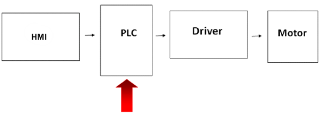
Programmable Logic Controller Block Diagram
Physical Properties of a Programmable Logic Controller
Although the programmable logic controller replaced the use of thousands of mechanical devices like relays, counters, and timers, we can still view the programmable logic controller like a box full of these devices but now integrated with data storage locations. These counters and timers don't really exist as hardware in our programmable logic controller, but rather they are simulated through software and are considered software counters and timers. The relays are also simulated through bit locations in registers.
CPU
The CPU (Central Processing Unit) is the most important component of a programmable logic controller. It controls the entire system based on the instructions stored in the programmable logic controller's memory. Anaheim offers four CPU lines offering different features based on your application's requirements.
Inputs
These are typically transistors and are connected to the outside world to receive signals from switches, sensors, buttons etc. Through photo coupler insulation all inputs are electrically isolated from the rest of the internal electronics. In Ladder Logic these are typically referred to as contacts.
Internal Utility Relays
These are simulated relays that eliminate the need to have external relays. Typically these are memory bit locations that can be toggled programmatically.
Counters
Counters are software based and are meant to count pulses which can count up, down, or both. Some manufacturers include high speed counters, which are hardware based.
Timers
These also do not physically exist because they are software-based and are meant to trigger something when time delay is finished or while the time delay is occurring. Increments may vary from 1ms through 1s.
Outputs
Outputs typically come in two forms transistor type or relay type. The relay type outputs work with both AC and DC loads but switch on and off at a much slower rate than transistors. The transistor type output can only switch a dc current and comes in either a NPN or PNP package. Common types of transistors manufacturers will use are BJT and MOSFET. A BJT cannot take as big a load as a MOSFET but can switch at a slightly faster rate. The output sequence is determined in the CPU program.
Memory
The programmable logic controller has RAM (Random Access Memory) and ROM (Read Only Memory). The set of written instructions for the programmable logic controller is stored in the RAM. The ROM includes the permanent programs like those that monitor the status of each input and output.
Programmable Logic Controller TYPES
PLCs are available in two primary designs: Modular and fixed I/O. A modular PLC may or may not have I/O on the board, but still allow for additional I/O cards to be integrated. A modular PLC typically utilizes a proprietary base to house all modules of the PLC system. In a fixed I/O PLC, the PLC itself is equipped with a finite number of I/O; a fixed I/O cannot be expanded beyond the I/O points that it comes with. Sometimes the PLC will attach to additional I/O cards through a proprietary connector. The proprietary base or connector will be used to power the additional units as well as provide a communication gateway. A modular PLC provides the system integrator with a tremendous amount of flexibility; in the case of a system update the integrator can simply purchase additional I/O cards. When it comes to selecting a fixed or modular PLC, it comes down to the total number of I/O points and the total number of future needed I/O points. If the system is not anticipated to change and its requirements of 4 inputs and 5 outputs, then a fixed I/O PLC would be perfect. Fixed I/O PLCs offer an economical solution in comparison to modular PLCs and oftentimes can perform most of the same functions equally as efficiently.
Programmable Logic Controller Applications
A programmable logic controller is specifically designed for use in industrial applications like the following:
- Production Processes
- Packaging Lines
- Pneumatic Machines
- Hydraulic Machines
- Refining Processes
- Traffic and Signal Systems
- Robotics
History of the Programmable Logic Controller
The first programmable logic controller (MODICON 084) was developed in the late 1960's by Bedford Associates. The introduction of the product was in response to General Motors' proposal for an electronic replacement for the thousands of relays, cam timers, drum sequencers, and dedicated closed-loop controllers needed to operate their automobile production line. Every year electricians rewired every relay due to model changeovers and the inherently short lifetime of the devices, making this change very urgent. Ladder logic was a great programming platform for programmable logic controllers because the visual representation of the circuit made it extremely easy for maintenance and for plant engineers to pick up on. Now the IEC1131-3 standard has merged various programmable logic controller programming languages in an effort to internationally standardize programmable logic controller programming languages.
Module Types
DISCRETE IO Module
A discrete I/O module is an attachment card for a modular PLC which serves two functions, it provides the ON and OFF status of an input and toggles an output ON and OFF. Discrete I/O modules can be all inputs all outputs or a combination of both. Discrete inputs can be sinking or sourcing and discrete outputs can be transistor or relay-type. Sometimes units will include the option to select sinking or sourcing, other times it may only be one or the other. Sinking inputs require the user to apply a voltage to activate the input. Sourcing inputs require the user to apply a ground signal on the pin to activate. Transistor output modules are DC outputs, typically smaller loads that provide fast switching times. Relay outputs operate well with AC or DC, and can handle large loads but switch at a much slower rate. Most discrete I/O modules are photo-coupler insulated to protect from inrush current.
ANALOG I/O MODULES
Analog I/O modules are meant to read or provide a certain voltage/current level. They have two uses: Analog to Digital Conversion (ADC) or Digital to Analog Conversion (DAC). ADC will allow the ability to read the current voltage/current level at your input. ADC units come in various resolutions; 8, 10, 14 and 16-bit are just a few examples. There must be a maximum reference voltage set so that we know what voltage our digital value translates to. For example let say I have an 8-bit ADC converter and I set my max voltage to 5 VDC, when I read the input I will receive a digital value between 0 and 255 (28). That value would then be multiplied by 0.019607 (VDCmax/255) to give us our voltage value at the pin. For a DAC module we would input the digital value (VDesired/0. 19607), and the DAC module would output that particular voltage. These modules are great for sensors with voltage outputs or Brushless Drives with Voltage speed inputs.
RESISTANCE TEMPERATURE DETECTION (RTD)
A Resistance Temperature Detector (RTD) sensor is a type of temperature sensor with a resistance value that changes as the temperature changes. For years, RTD sensors have been used to measure temperature in laboratory and industrial processes. Over time, RTD sensors have developed a reputation for accuracy, repeatability and stability. With the use of RTD sensors and an RTD module, the PLC can convert that resistance value into a digital value. Once the resistance input has been converted, the digital value can now be used in the Ladder Logic program as a condition or can be converted to Celsius or Fahrenheit. Some applications require the RTD feedback for PID purposes and other's simply need to monitor the temperature. Typically RTD sensors are made of platinum in order to withstand extreme temperatures. Other RTD materials are nickel, copper and nick-iron alloy, which are not as commonly used since they cannot handle extreme temperatures like platinum can. There are two standards when it comes to RTD sensors: European and American. The European Standard is the most common and adopted world-wide; it requires the sensor to have a 100 ohm resistance at 0˚C, as well as have a temperature coefficient of resistance of 0.00385 ohm/ohm/C between 0˚C and 100˚C. The American standard which is mostly used in North America has a resistance of 100.00 ± 0.10 ohms at 0˚C and a temperature coefficient of resistance of 0.00392 ohm/ohm/C between 0˚C and 100˚C.
THERMOCOUPLE (TC)
A thermocouple is a temperature sensor that consists of two dissimilar metals joined together at one end. When the junction is heated or cooled a voltage is produced that can be correlated back to temperature. Commercial thermocouples are inexpensive, interchangeable, are supplied with standard connectors, and can measure a wide range of temperatures. The biggest limitation that thermocouples have is accuracy; it can difficult to achieve errors of less than one degree. A TC module would process the voltage from the TC and turn it into a digital value for use in Ladder Logic.
THERMISTOR
A thermistor is a type of resistor whose resistance value changes greatly with temperature. The difference between an RTD sensor and a thermistor is the material they are made of. While an RTD sensor is made up of alloy, thermistors are generally made of ceramic or polymer. Thermistors can achieve a much more accurate reading but are limited in their range. A thermistor module in a PLC system can convert the resistance at the input pin to a digital value for use in Ladder Logic.
HIGH SPEED COUNTER
Oftentimes PLCs come stock with High Speed Counters but this isn't always the case. There are two types of high speed counters for PLC systems, Line Driver and Open Collector. An open collector high speed counter will receive the pulled up collector output and read every rising or falling edge. Open collector high speed counters are often-times more economical because of their prevalence and simple design. Typically an open collector high speed counter is limited to a cable length below 30ft. Line Driver High speed counters deploy differential signaling to reduce noise. Along with the differential signaling scheme, some manufactures shield the lead wires so that communication lengths can be drastically increased and still remain immune to noise. Even if the PLC is equipped with high speed counters the customer may require more than what they are given, which is why it is common for PLC manufacturers to sell high speed counter modules. It is important to always buy a high speed counter module from the same PLC manufacturer. Ensure that the high speed counter max frequency input is greater than frequency coming from your system.
REDUNDANCY
A PLC Redundancy System is meant to make your system completely fail-safe! A Redundancy system can protect you from power failure and communication failure as well as protection from PLC errors. System Redundancy is useful for applications that require zero down time, operate 24/7, or can put lives at risk if the system fails, such as water dams, chemical manufacturers, and airport traffic control. The Redundancy system typically requires that you have two bases-a primary and secondary-which include a power supply, power monitoring module, redundancy CPU, redundancy interface, redundancy communication module, and a base to house all modules. To protect your system from power failure, the Power Monitoring Module connects to the 24VDC output of the redundancy power supply and notifies the user in the event of power failure. If complete power failure occurs, the secondary unit will become the master and continue operation in a very small time frame. To further protect your system from power failure you can purchase a redundancy base which will permit you to have two power supplies on one base, so if one power supply goes bad the other one will continue powering the base. A redundancy interface module will assign the two bases priority, either Primary or Secondary, and sometimes offer a test feature which will force the system to switch from the Primary over to the Secondary, and vice-versa. The redundancy communication module is vital to the redundancy system; this module transfers the current running program from the Primary to the Secondary CPU scan-by-scan so if a system failure were to occur the Secondary unit would continue operation shortly after.
PLC Communication
RS-232
The most common method of communication utilized in the industrial work is RS-232. RS-232 is an asynchronous communication method that requires 3 wires: Receive, Transmit and Ground. The signal being carried across the wires is ±15 volt, where the voltage between ±3 volts is just considered noise. A positive voltage above 3 volts is considered to be a MARK and a negative voltage below 3 volts is SPACE. MARK and SPACE date back to Morse code; when the needle contacted the paper, the word MARK would be called and when the needle bounced, the word SPACE was called.
There are two RS-232 device types; DTE and DCE. Data Terminal Equipment (DTE) is a computer; a device that sends outputs and reads inputs. Data Communications Equipment (DCE) is a modem, something that acts as a gateway. The connector itself is available in numerous packages; DB9, DB25 and RJ11, to name a few.
The RS-232 communication package is comprised of 1 byte and a start and stop bit. The start bit signifies the beginning of communication. The stop bit signifies the termination of communication. With-in the time frame of receiving the start bit and receiving the stop bit, the data byte is being transmitted. The most significant bit in the data byte is the parity bit, which is used for error-checking. Parity will tell you if the number of ones in the preceding 7 bits is even or odd. There are various speeds at which you can communicate, called the baud rate. The baud rate speeds are interpreted as bit- per-second being transmitted, and some common speeds are as follows: 1200, 2400, 4800, 9600, 19200 and 38400. Commonly used in RS-232 communication is a delimiter which notifies us at the end of a transmission sequence. This is useful to know because upon receiving a delimiter we can now begin to process the data received. Common delimiters are Carriage Returns (CR) or Carriage Returns plus a Line Feed (CR+LF) which translates to 0x0D and 0x0D0A, respectively. The term, "carriage return" comes from the typewriter days when you would have to manually return the carriage to its starting position (left side of the paper) when you reached the end of the line. "Line feed" also comes from the typewriter era; it lowered the carriage so that you would not type over your already-typed material.
RS-485
RS485 PLC systems are interesting because the RS485 standard enables the configuration of inexpensive local networks and multi-point communications links, whereas RS232 PLC systems are only point-to-point. PLC systems using the RS485 standard have the capability to communicate at speeds of 35 Mbps up to 10M and 100 Kbps at 1,200m. A good rule of thumb for the speed-to-distance ratio is that the speed in Mbps multiplied by the length in meters should not exceed 108. For example, in a PLC system, a 50 meter cable should not signal faster than Mbps. The RS-422 standard is much like the RS-485 standard in that they are both differential signals and can be made full-duplex. PLC systems employing a full-duplex standard can send and receive at the same time while systems using a half-duplex system must receive a packet and then send an acknowledgment (ACK). Because of the ACK a half-duplex system cannot send/receive simultaneously. Oftentimes the deployed environment might not have an Ethernet network, forcing the system integrator to build a RS-485 network. Each signal is transmitted over a plus and minus line and the receiver compares the voltage difference between the two lines, whereas RS232 simply gets the absolute voltage on the line. The differential signaling method is much more effective in reducing noise because there is no need for a ground level reference. For added noise immunity the cables can we twisted and shielded just like STP (Shielded Twisted Pair) and FTP (Foiled Twisted Pair) networking cables.
RS-422
RS422 is a serial, balanced differential standard that defines the electrical characteristics of a digital signaling circuit. This differential signaling scheme can transmit up to 10 Mbps or extend up to 1,500 meters. As wire lengths increase, the speed must decrease or data loss may occur. RS-422 is multi-drop, unlike RS-485 which is a multi-point differential scheme. A multi-drop system is similar to a master/slave relationship, whereas the master is the only driver in the system and the slaves are all receivers. The multi-drop scheme prevents the slaves from transmitting data back. RS-422 can connect with up to 10 receivers in parallel.
PROFIBUS
PROFIBUS is a communication standard for field bus devices, standing for Process Field Bus. It was first introduced in 1989 by the German department of education and research and later adopted by Siemens. It is important to note that PROFIBUS in not an Open Standard like MODBUS and is not royalty-free. PROFIBUS is a standardized, application-independent communication protocol. The standard now supports fieldbus solutions both in factory and process automation as well as in motion control and safety related tasks. Today there are two versions of PROFIBUS: the most commonly used PROFIBUS DP, and the lesser used PROFIBUS PA. PROFIBUS DP is used to operate sensors and actuators, whereas PROFIBUS PA is used to monitor measuring equipment. PROFIBUS is modularly structured with communication protocol as the core component. The PROFIBUS structure has various application profiles for PA Devices, Encoders, Weighing & Dosage, etc. These application profiles commonly use the RS485 standard as the transmission technology.
DNP3.0
DNP 3.0 was created by the partially completed IEC 60870-5 protocol to provide a standardized communication protocol between components in HMI/PLC systems. This communication protocol is very popular in HMI/PLC systems that employ SCADA. DNP 3.0 provides SCADA with all the pertinent information from the RTU (Remoter Terminal Units) or IEDs (Intelligent Electronic Devices). The DNP 3.0 protocol is designed to allow HMI/PLC systems to reliably communicate in high EMI (Electro-Magnetic Interference) areas. Initially DNP 3.0 could not provide HMI/PLC systems with security from hackers, but now it is compliant with IEC 62351-5 which employs secure authentication features.
A DNP 3.0 system consists of two main items: a master and an outstation. The master is a device that queries an outstation database for information to store in its own database. An outstation is typically an RTU or an IED. Typical master input data types are binary, analog and counter. It is the master's objective to keep its database updated; it does this by polling outstations. The outstation will respond to the master's request by transmitting the contents of it database. The HMI/PLC architecture is unique to the application but with the DNP 3.0 protocol all of the following are possible: peer to peer, multi-drop, master-to-master-to-outstation and master-to-outstation-to-master. Many vendors offer products that utilize TCP/IP to transport DNP3 messages.
When employing TCP/IP to transport DNP3 messages, we must follow the OSI model. The OSI link layer is responsible for sending the frames. Frames are the packets the DNP 3.0 messages are transmitted in. The frame consists of a header and data section which holds the DNP 3.0 information. The header consists of two sync bytes, the number of bytes in the frame, a link control byte for coordinating, sending and receiving, destination and source addresses, and a CRC for error detection. When transmitting large amounts of data, the transport layer will divide data into multiple frames to conform to TCP/IP standards.
Industrial Ethernet
Ethernet is a local area network that provides communication between devices at speeds between 10 Mbps to 100 Gbps. The physical communication media you use can be any standard 802.3 media, including thick-wire coaxial cable (10Base5), thin-wire coaxial cable (10Base2), twisted pair (10Base-T), fiber-optic, and broadband. The clear benefit of an Ethernet-based system is in the increased speed, increased communication distance, and multiple nodes on a link. Some of the difficulties with deploying an Ethernet-based plc system are migrating current systems to a new protocol. Managing a TCP/IP stack is more complex than just receiving serial data because the minimum Ethernet frame size is 64 bytes, while serial communication is typically 1-8 bytes.
MODBUS
This protocol is commonly used by PLCs to query information from Industrial Electronic Devices (IED). MODBUS was developed with industrial applications is mind and has therefore been widely adopted. This protocol is openly published and royalty-free; OEMS can deploy MODBUS functionality to their IEDs at no cost. MODBUS can communicate with up to 247 devices on the same network but if both the MODBUS Master and all of the slaves support extended addressing, there can be 65,535 devices on one network. Serially only the MODBUS Master can transmit MODBUS commands but in Ethernet networks, slaves can issue MODBUS commands. Each device on the network has a unique ID so the master can query individually. MODBUS can be thought of as a standardized excel spreadsheet template; rows A0-AN displays one type of data, rows B0-BB displays another, etc. The MODBUS protocol is a standardized packet of information that allows us to store or retrieve data from the excel spreadsheet. MODBUS packages its query into three different formats: MODBUS RTU, MODBUS ASCII, and MODBUS TCP. Some of the basic instructions MODBUS offers include: the ability to a register in an RTU device, control or read an I/O port, or request a register from the RTU. Every MODBUS instruction is finished with an LRC, CRC, or checksum.
PLC Features
It is very common for PLCs from different manufacturers to have the same or similar features, such as a Real Time Clock, USB or SD slot for additional memory, multiple communication ports, USB loader, high speed counters, and pulse train outputs just to name a few. When selecting a PLC, taking its features into account is extremely important to avoid purchasing more features than your application requires. Thoroughly laying out application requirements before purchasing ensures the developer selects a PLC with all the right features. A real-time clock is used for applications that must reference the time of day, use alarms, generate production reports, or schedule maintenance. USB and SD slots are great for data intensive applications such as data loggers. Oftentimes applications require communication with multiple devices for that reason vendors offer plenty of variety in their communication options. Some applications only may require peer-to-peer communication where an RS-232 port would suffice but others may need to communicate with 10 devices where an RS-485 or Ethernet port would be better suited. When it comes to programming the most common standard today is USB, however some PLCs still only have an RS-232 port; whether the developer would like to purchase a PLC with a USB or RS-232 loader is completely preference. Other features such as high-speed counters and pulse train outputs are completely dependent on the application. High-speed counters would be needed if a pulse train was being fed to the PLC's input and a pulse train output would be needed if running a stepper or servo motor.
PLC Number Systems
PLCs view and output data via number systems – primarily in binary, hexadecimal, and decimal format. Each number system has a conversion method to and from another number system and that conversion method is pretty similar for all of them. For humans, the decimal number system is what we utilize day in and day out but it is not much different from binary, hexadecimal, and octal. The decimal number system comprises of characters 0 through 9 and is raised 10 to the n power. The base for the decimal system will always be 10 and the exponent depends on the displacement from the decimal point. All other numbers systems work in a similar fashion; they have their unique character set as well as unique base. At the heart of the PLC all data is processed in 1's and 0's (Binary) the reason being, it is much quicker to process two characters but requires many more digits to be processed. Hexadecimal is very common in PLC's although there are now 16 characters to process but the number of digits to process are much less.
Decimal
D = decimal character (0 through 9)
10 = base
N = exponent that starts at 0 and increases by one each time a new D is added to the left of the decimal point
Dvalue*10n+ Dvalue*102+ Dvalue*101+ Dvalue*100 = Dtotal
E.G.
125DEC = 1*102+2*101+5*100 = 100+20+5 = 125
Binary
B = binary character (0 or 1)
2 = base
N = exponent that starts at 0 and increases by one each time a new B is added to the left of the decimal point
Bvalue*2n+ Bvalue*22+ Bvalue*21+ Bvalue*20 = Btotal
E.G.
0111 1101BIN = 0*27+ 1*26+ 1*25+ 1*24+ 1*23+ 1*22+ 0*21+ 1*20 = 0*128 + 1*64 + 1*32 + 1*16 + 1*8 + 1*4 + 0*2 + 1*1 = 0 + 64 + 32 + 16 + 8 + 4 + 0 + 1 = 125DEC
Hexadecimal
H = hexadecimal character (0 through 9 A through F)
16 = base
N = exponent that starts at 0 and increases by one each time a new H is added to the left of the decimal point
Hvalue*16n+ Hvalue*162+ Hvalue*161+ Hvalue*160 = Htotal
E.G.
7DHEX = 7*161 + D*160 = 7*16 + 13*1 = 125DEC
Octal
O = octal character (0 through 7)
8 = base
N = exponent that starts at 0 and increases by one each time a new O is added to the left of the decimal point
Ovalue*8n+ Ovalue*82+ Ovalue*81+ Ovalue*80 = Ototal
175OCT = 1*82 + 7*81 + 5*80 = 64 + 56 +5 = 125DEC